T-S Diagram Heat Engine

Thermodynamics is a branch of physics which deals with the energy and work of a system. Thermodynamics deals with the large scale response of a system which we can observe and measure in experiments. As aerodynamicists, we are most interested in the thermodynamics of propulsion systems and high speed flows. The propulsion system of an aircraft generates thrust by accelerating a working fluid, usually a heated gas. In response to Newton's third law of motion, the propulsion system and the aircraft are accelerated in the opposite direction. To understand how a propulsion system works, we must study the basic thermodynamics of the working fluid.
The working fluid of a propulsion system is a gas. Gases have various properties that we can observe with our senses, including the gas pressure p, temperature T, mass, and volume V that contains the gas. Careful, scientific observation has determined that these variables are related to one another, and the values of these properties determine the state of the gas. The first and second laws of thermodynamics define two additional variables, enthalpy and entropy S, which can also be used to describe the state of a gas. A thermodynamic process, such as heating or compressing the gas, changes the values of the state variables in a prescribed manner. The total work and heat transferred to a gas depend on the beginning and ending states of the gas and on the process used to change the state.
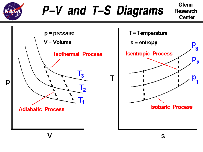
It is useful to plot the changes in the state of a gas during a thermodynamic process. On the figure we show two types of plots that are used to describe changes of state. On the left we have plotted the pressure versus the volume, which is called a p-V diagram. On a p-V diagram, lines of constant temperature curve from the upper left to the lower right. A process performed at constant temperature is called an isothermal process. During an adiabatic process no heat is transferred to the gas, but the temperature, pressure, and volume of the gas change as shown by the dashed line. As described on the work slide, the area under a process curve on a p-V diagram is equal to the work performed by a gas during the process. On the right of the figure we have plotted the temperature versus the entropy of the gas. This plot is called a T-s diagram. Lines of constant pressure curve from the lower left to upper right on a T-s diagram. A constant pressure process is called an isobaric process and this type of process occurs in the combustor of a gas turbine engine. During an isentropic process there is no change in the entropy of the system and the process is reversible. An isentropic process appears as a vertical line on a T-s diagram. The area under a process curve on a T-s diagram is related to the amount of heat transferred to the gas.
It is possible to perform a series of processes, in which the state is changed during each process, but the gas eventually returns to its original state. Such a series of processes is called a cycle and forms the basis for understanding engines. The Carnot Cycle describes the operation of refrigerators, the Otto Cycle describes the operation of internal combustion engines, and the Brayton Cycle describes the operation of gas turbine engines. P-V and T-s diagrams are often used to visualize the processes in a thermodynamic cycle and help us better understand the thermodynamics of engines.
Activities:
Guided Tours
Navigation..
- Beginner's Guide Home Page
Source: https://www.grc.nasa.gov/www/k-12/airplane/pvtsplot.html
Posted by: marylynmarylynszymanskie0270847.blogspot.com
Post a Comment for "T-S Diagram Heat Engine"